9. E-Textiles and Wearables II#
This week I worked on the second round of Electronics and E-Textiles. Well, more or less..
Introduction to Electronics 2.0#
First day of this week’s assignment, was introduction to more very interesting knowledge about the subject with the lovely Emma teaching us. I learned how to use the ATtiny with the Arduino, and program it by writing the accurate codes. After figuring out how it works we could finally lighten up an LED, as well as Neo-pixels; but also turn on a vibration- and a sound motor.
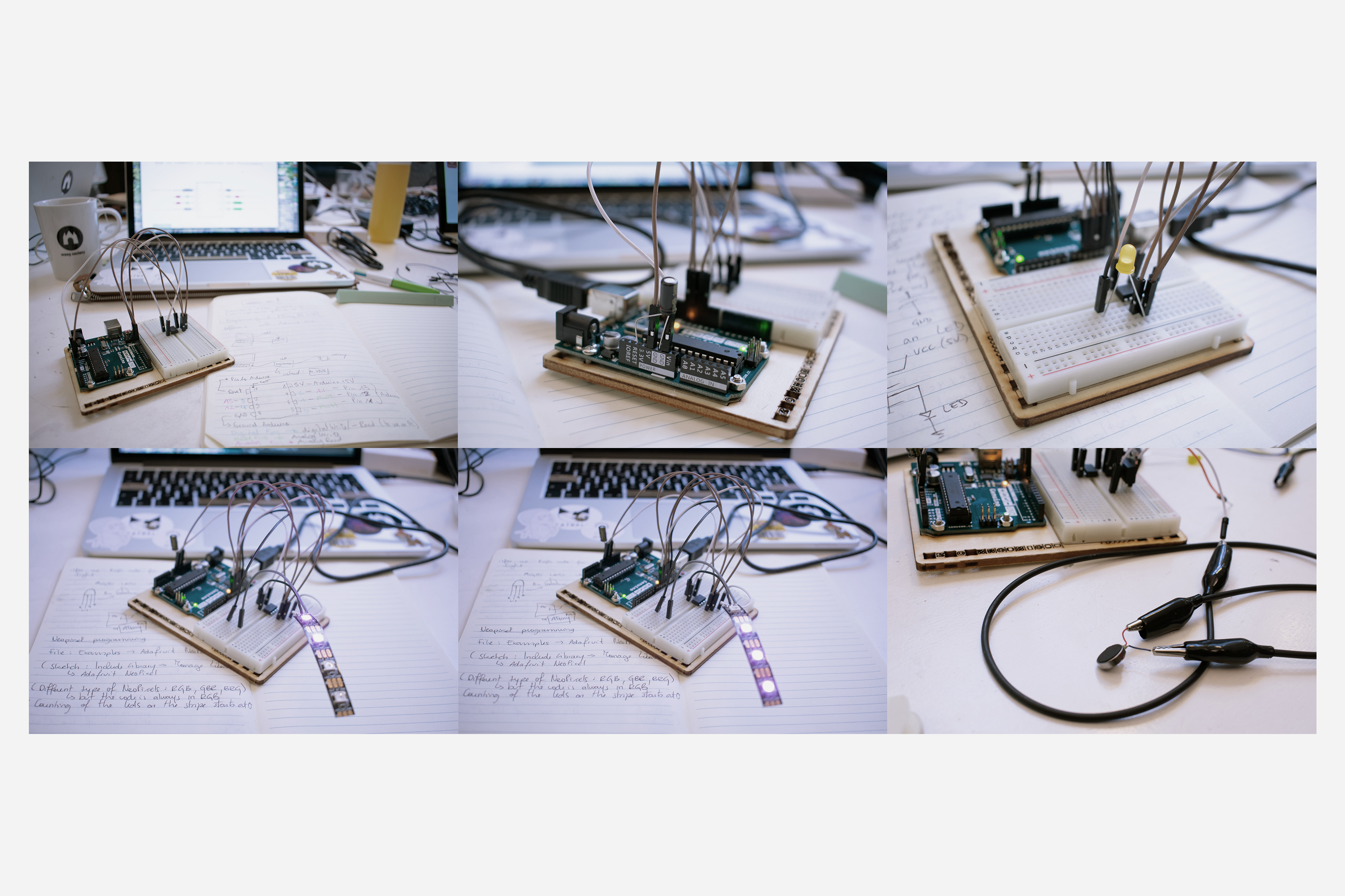
Useful tool#
I found it useful to create a specific circuit on a piece of cardboard with a transistor as an electric switch (MOSFET), that could be used over and over again for different types of circuit samples. It’s a ‘Nice-to-have’ !
![]()
Here, you use the transistor as an electrical switch. By applying a small amount of voltage to the gate using the Arduino, current can flow between the drain and the source.
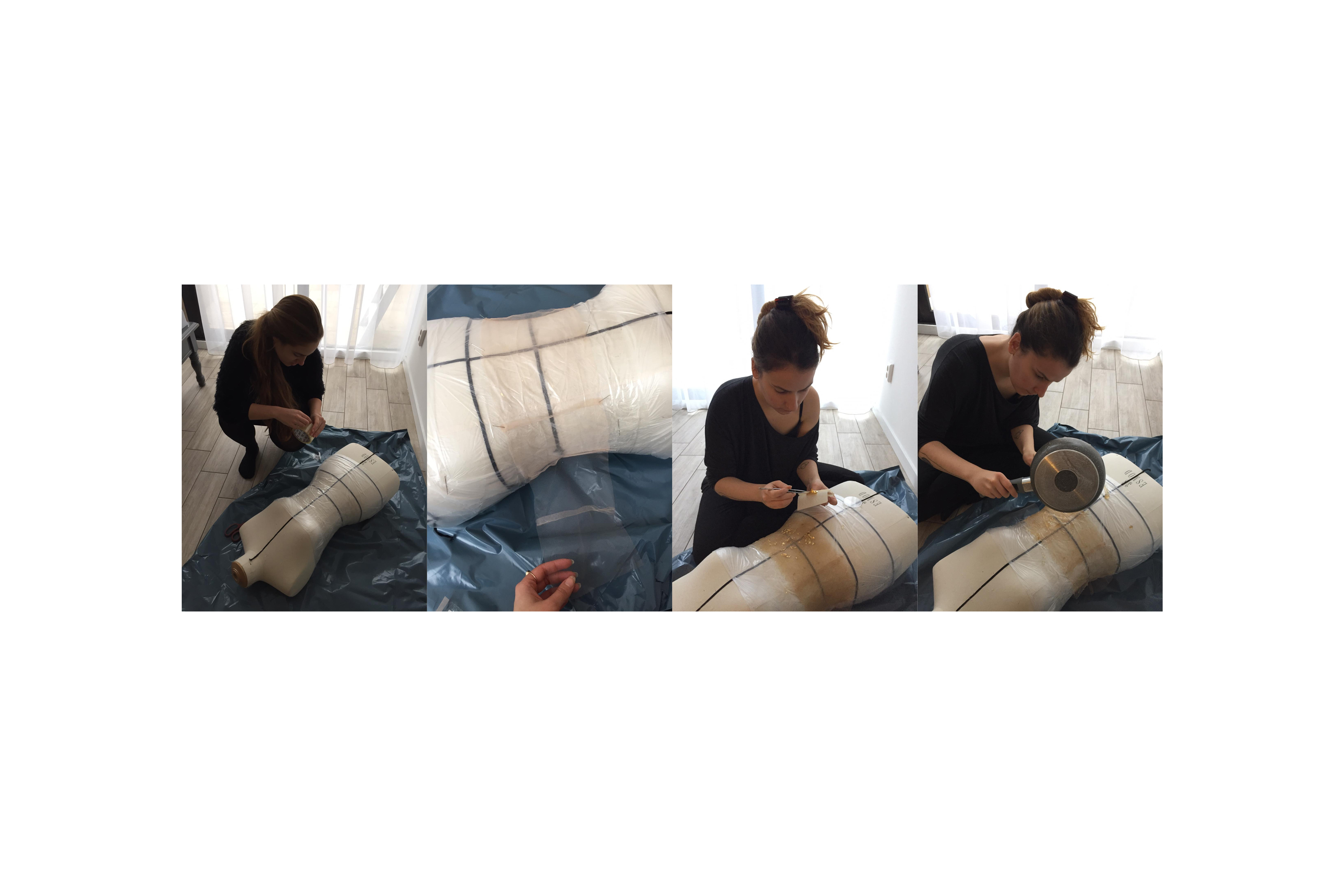
My little Swatch#
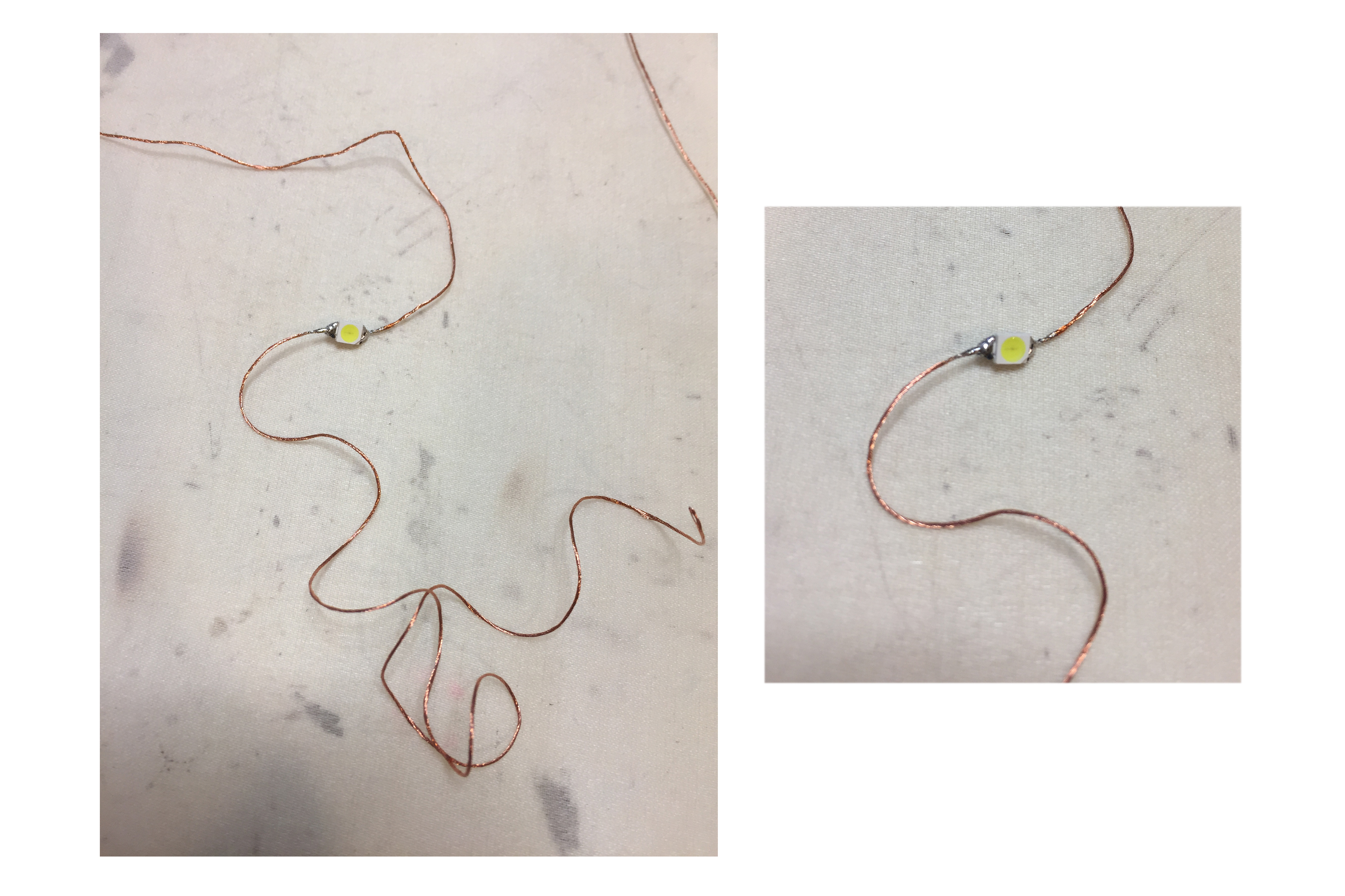
My idea for this assignment was to get more into LED programming and also to learn about integrating them onto fabric. I thought embroidering them with conductive thread by soldering the elements together, may be a nice start. Also quick note : I enjoy the soldering process very much ! So, I picked up a piece of fabric, some copper thread, a niddle, and a few Surface mount (SMD) LEDs (3mm, PLCC 3528).
( Info: SMD LEDs ar esuper tiny and great for embedding light discreetly.The sizes vary from 1mm up to 5mm.)
I quickly learned how to handle the soldering of the tiny LEDs onto the copper thread, and because it’s a task that requires precise work it took quite some time but I really liked the process!
After soldering the first one, I started to stitch onto a piece of fabric and added the second one, continued the embroidery, added third one, etc.
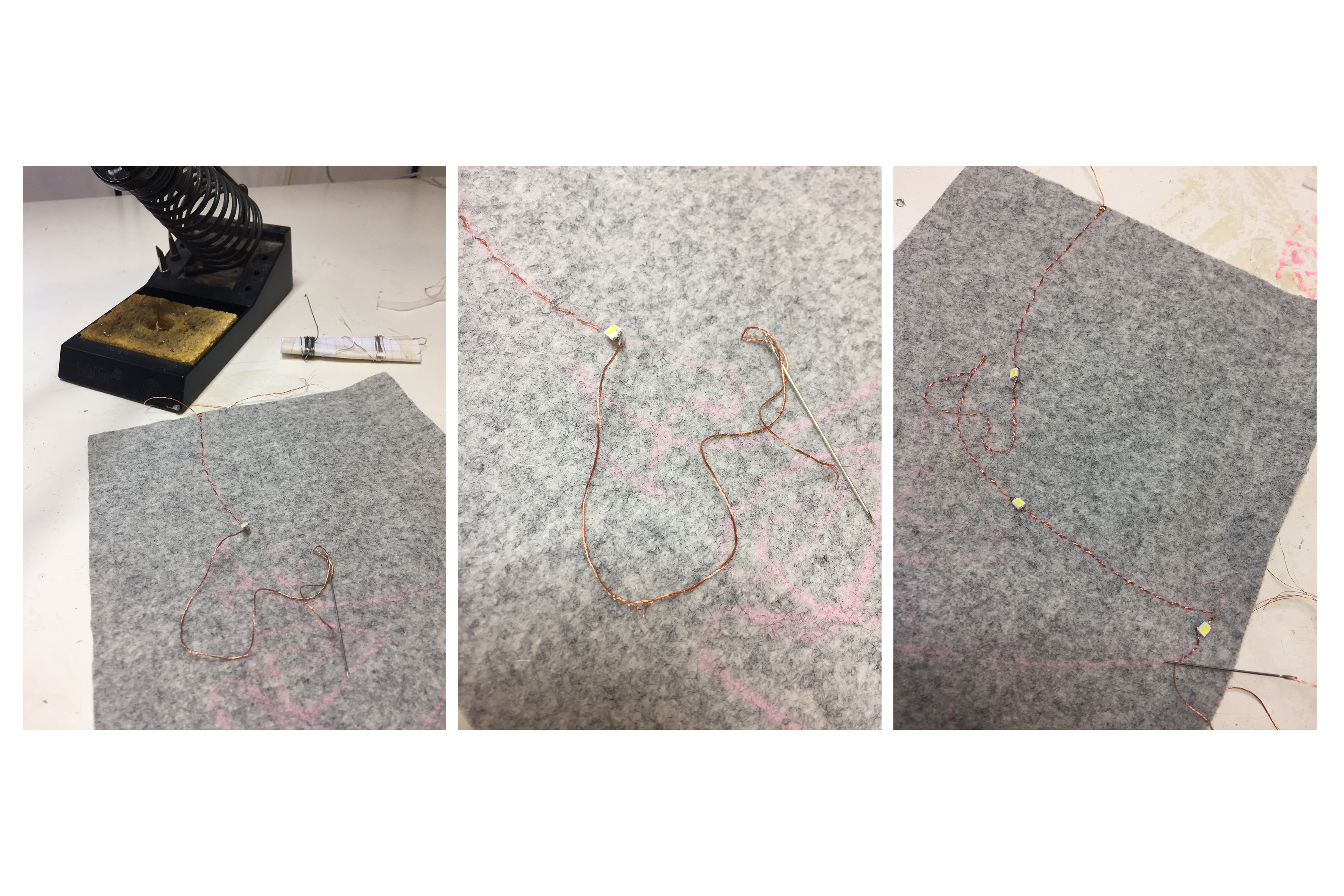
Finally, I ended up with a face embroidery with 4 SMD LEDs.
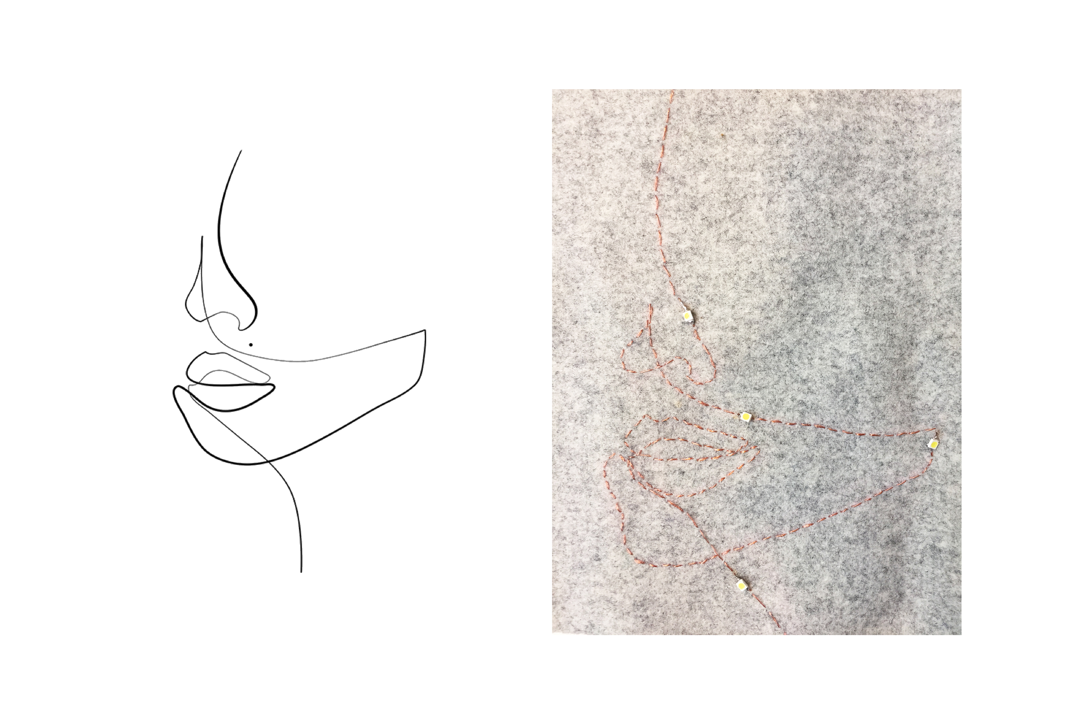
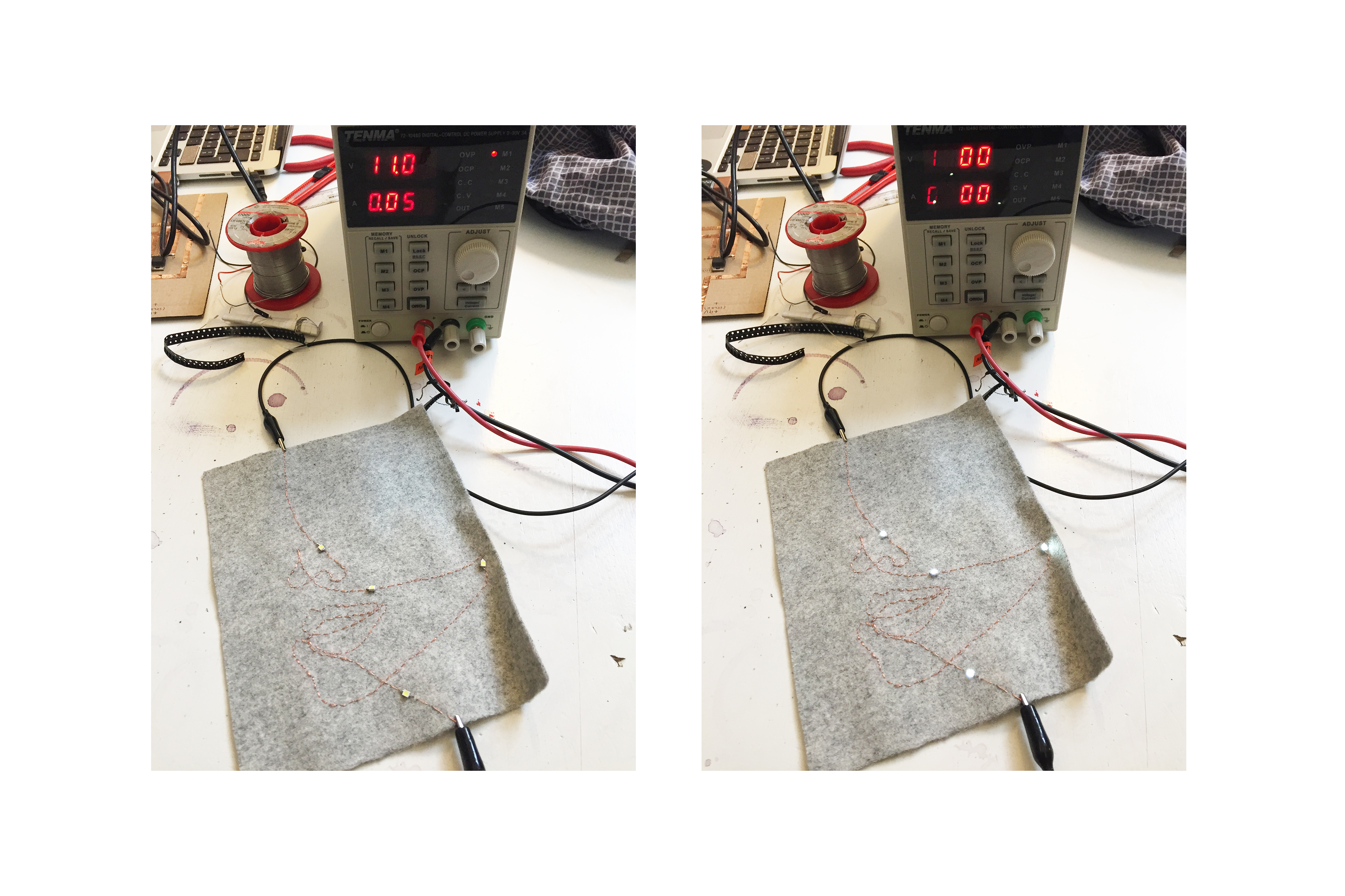
Now it’s time to test the sample!

It works! Well, I had to use the ?? and input 11V into the circuit in order to get all 4 LEDs on. Under 9V it’s unfortunately not enough, as I wanted to use a circuit with a 9V battery..
Simple Code#
With a power source of 11V, you can program the ATtiny to control the circuit. Very basic code to switch it On-Off would be the following :
//* Stéphanie Santos; LED on-off code
// November 2018
// E-textiles & Wearables 2

int led_pin = 1; // pin of the LED
void setup() {
  // put your setup code here, to run once:
  pinMode(led_pin, OUTPUT);

}

void loop() {
  // put your main code here, to run repeatedly:

  digitalWrite(led_pin, HIGH); //turn on the LED
  delay(100); //wait 100ms
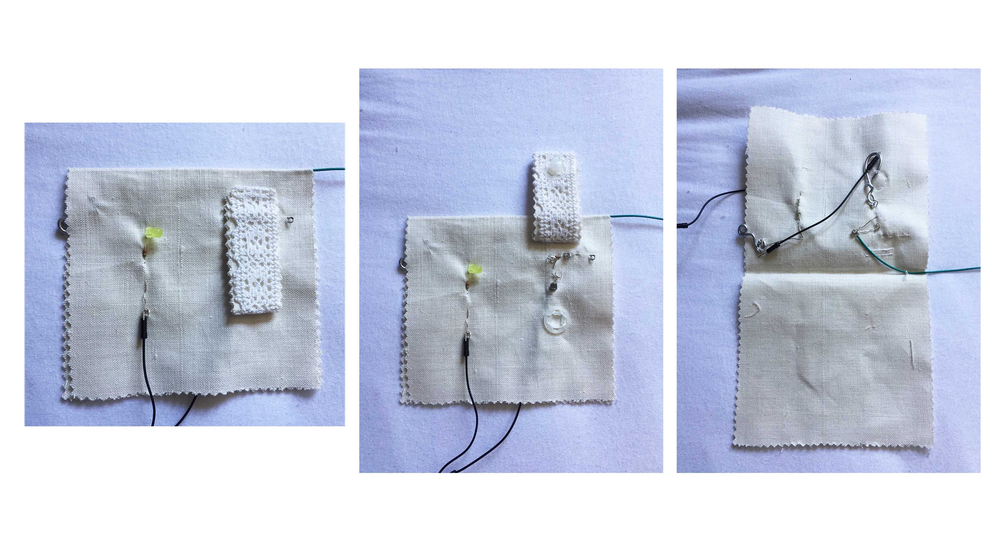
Light Sensor woth Arduino#
I decided to translate this circuit into a E-textile. I used : - linen fabric - silver wire - plastic snap-button
Below you can find what is needed for the Electronics part :
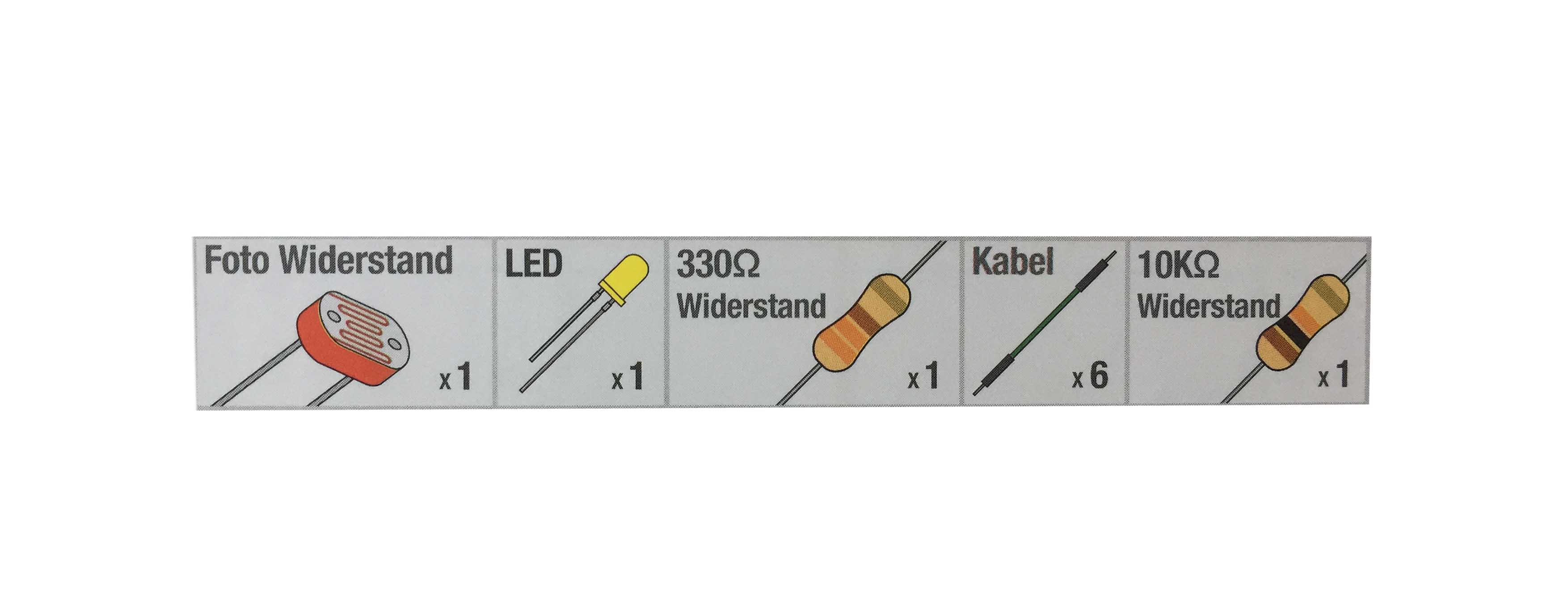
Build the circuit :#
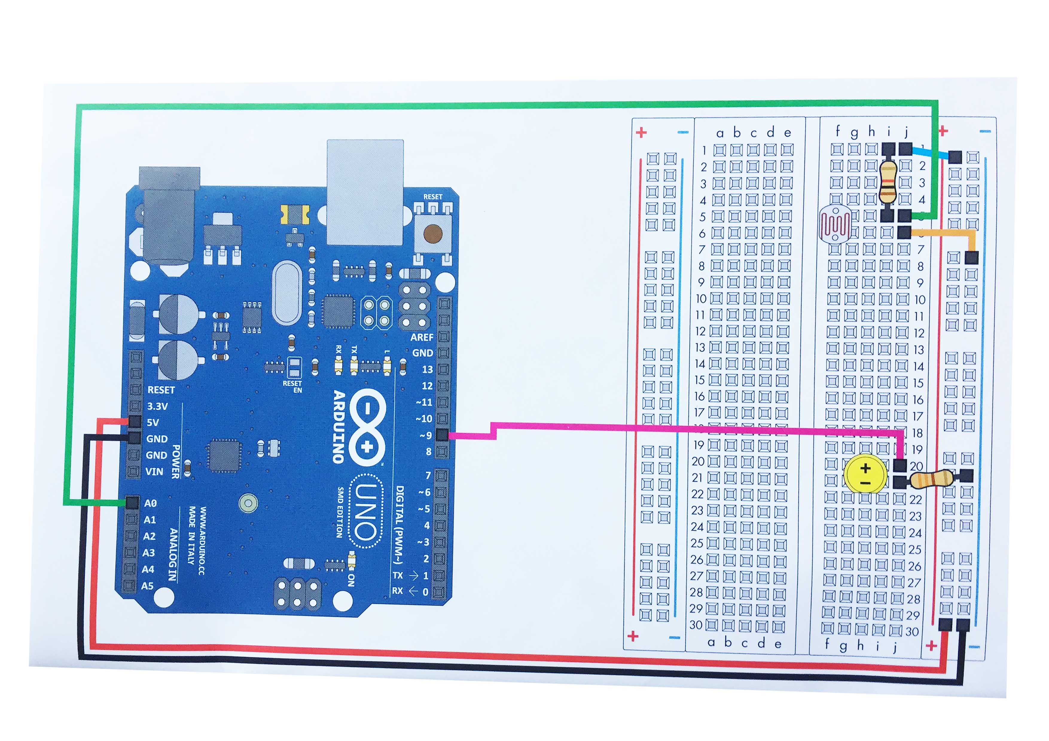
PHOTO RESISTOR
Use a photoresistor (light sensor) to control the brightness of a LED.
Hardware connections:
Photo resistor:
Connect one side of the photoresistor to 5 Volts (5V).
Connect the other side of the photoresistor to ANALOG pin 0.
Connect a 10K resistor between ANALOG pin 0 and GND.

This creates a voltage divider, with the photoresistor one
of the two resistors. The output of the voltage divider
(connected to A0) will vary with the light level.
LED:
Connect the positive side (long leg) of the LED to
digital pin 9. (To vary the brightness, this pin must
support PWM, which is indicated by "~" or "PWM" on the
Arduino itself.)

Connect the negative side of the LED (short leg) to a
330 Ohm resistor.

Connect the other side of the resistor to GND.
Circuit :

My attempt :#

Transformed into E-textile :#

The instructions for the circuit can be found on the ‘instructions book’ by Vilros Arduino kit for starters . You can download the full version of the code here : Code circuit 6
This sketch was written by SparkFun Electronics, with lots of help from the Arduino community. This code is completely free for any use. Visit Arduino to learn about the Arduino.
Enjoy !
// Stéphanie Santos, 2019
// E-textiles 2, Fabricademy
// Light sensor to control LED brightness

const int sensorPin = 0;
const int ledPin = 9;

// We'll also set up some global variables for the light level:

int lightLevel, high = 0, low = 1023;


void setup()
{
  // We'll set up the LED pin to be an output.
  // (We don't need to do anything special to use the analog input.)

  pinMode(ledPin, OUTPUT);
}


void loop()
{
  // Just as we've done in the past, we'll use the analogRead()
  // function to measure the voltage coming from the photoresistor
  // resistor pair. This number can range between 0 (0 Volts) and
  // 1023 (5 Volts), but this circuit will have a smaller range
  // between dark and light.

  lightLevel = analogRead(sensorPin);

  // We now want to use this number to control the brightness of
  // the LED. But we have a problem: the analogRead() function
  // returns values between 0 and 1023, and the analogWrite()
  // function wants values from 0 to 255.

  // We can solve this by using two handy functions called map()
  // and constrain(). Map will change one range of values into
  // another range. If we tell map() our "from" range is 0-1023,
  // and our "to" range is 0-255, map() will squeeze the larger
  // range into the smaller. (It can do this for any two ranges.)

  // lightLevel = map(lightLevel, 0, 1023, 0, 255);

  // Because map() could still return numbers outside the "to"
  // range, (if they're outside the "from" range), we'll also use
  // a function called constrain() that will "clip" numbers into
  // a given range. If the number is above the range, it will reset
  // it to be the highest number in the range. If the number is
  // below the range, it will reset it to the lowest number.
  // If the number is within the range, it will stay the same.

  // lightLevel = constrain(lightLevel, 0, 255);

  // Here's one last thing to think about. The circuit we made
  // won't have a range all the way from 0 to 5 Volts. It will
  // be a smaller range, such as 300 (dark) to 800 (light).
  // If we just pass this number directly to map(), the LED will
  // change brightness, but it will never be completely off or
  // completely on.

  // You can fix this two ways, each of which we'll show
  // in the functions below. Uncomment ONE of them to
  // try it out:

  manualTune();  // manually change the range from light to dark

  //autoTune();  // have the Arduino do the work for us!

  // The above functions will alter lightLevel to be cover the
  // range from full-on to full-off. Now we can adjust the
  // brightness of the LED:

  analogWrite(ledPin, lightLevel);

  // The above statement will brighten the LED along with the
  // light level. To do the opposite, replace "lightLevel" in the
  // above analogWrite() statement with "255-lightLevel".
  // Now you've created a night-light!
}


void manualTune()
{
  // As we mentioned above, the light-sensing circuit we built
  // won't have a range all the way from 0 to 1023. It will likely
  // be more like 300 (dark) to 800 (light). If you run this sketch
  // as-is, the LED won't fully turn off, even in the dark.

  // You can accommodate the reduced range by manually
  // tweaking the "from" range numbers in the map() function.
  // Here we're using the full range of 0 to 1023.
  // Try manually changing this to a smaller range (300 to 800
  // is a good guess), and try it out again. If the LED doesn't
  // go completely out, make the low number larger. If the LED
  // is always too bright, make the high number smaller.

  // Remember you're JUST changing the 0, 1023 in the line below!

  lightLevel = map(lightLevel, 500, 800, 0, 255);
  lightLevel = constrain(lightLevel, 0, 255);

  // Now we'll return to the main loop(), and send lightLevel
  // to the LED.
}


void autoTune()
{
  // As we mentioned above, the light-sensing circuit we built
  // won't have a range all the way from 0 to 1023. It will likely
  // be more like 300 (dark) to 800 (light).

  // In the manualTune() function above, you need to repeatedly
  // change the values and try the program again until it works.
  // But why should you have to do that work? You've got a
  // computer in your hands that can figure things out for itself!

  // In this function, the Arduino will keep track of the highest
  // and lowest values that we're reading from analogRead().

  // If you look at the top of the sketch, you'll see that we've
  // initialized "low" to be 1023. We'll save anything we read
  // that's lower than that:

  if (lightLevel < low)
  {
    low = lightLevel;
  }

  // We also initialized "high" to be 0. We'll save anything
  // we read that's higher than that:

  if (lightLevel > high)
  {
    high = lightLevel;
  }

  // Once we have the highest and lowest values, we can stick them
  // directly into the map() function. No manual tweaking needed!

  // One trick we'll do is to add a small offset to low and high,
  // to ensure that the LED is fully-off and fully-on at the limits
  // (otherwise it might flicker a little bit).

  lightLevel = map(lightLevel, low+30, high-30, 0, 255);
  lightLevel = constrain(lightLevel, 0, 255);

  // Now we'll return to the main loop(), and send lightLevel
  // to the LED.
}
Magnetic flip dot#
I was curious about the flip dots after watching Pauline van Dongen’s Flip dots jacket. So I decided to make an attempt, but as I was back home in Luxembourg (where I needed to catch up on this assisgnment), I realized my material supply was very limited.. This is what I made :
Fortunately, I had magnetic beads that I could use for the flip dot. I thought I could make it a bigger shape and create a crepy eye, while using the glue of a glue-gun. Also, the wire I used was a 1mm thick copper wire (coated) that I could get from my dad’s. Therefor, I only did about 10-15 loops to create the coil.
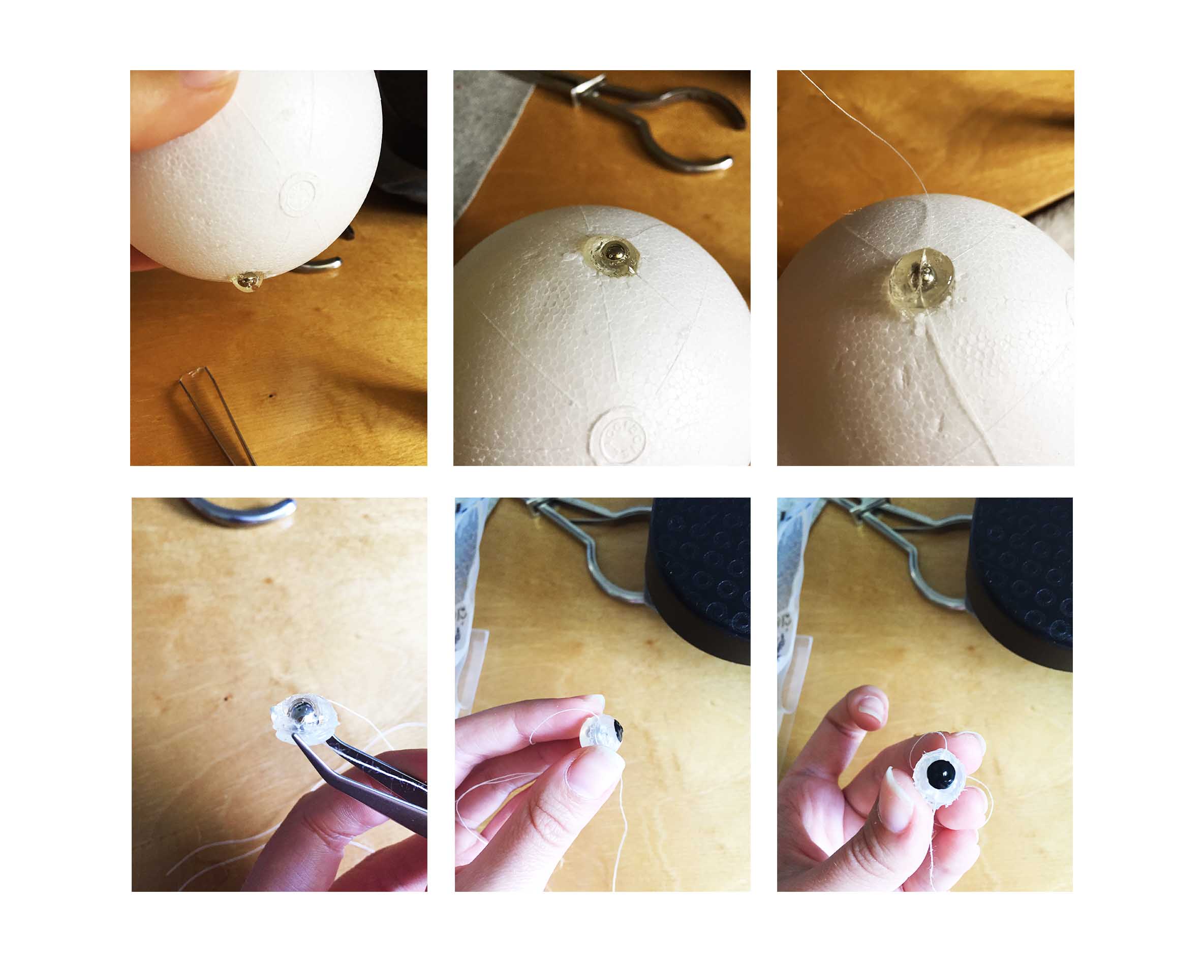
But as I tried it on the circuit, it didn’t flip. I thought it might be either the coil that wasn’t strong enough or the glue around was isolating the magnetic force of the bead too much..

So I tried it again with using directly the magnetic bead (without a coat around). And it worked. I used a 9V battery for this coil.

Meanwhile..#